Electronics Parts, LCC, et al
I mentioned in the previous post that I spent the last week or so doing diddly-squat on the layout. A few tests of the BOD, but otherwise more time was spent building a PoC (Proof of Concept) circuit for LCC (Layout Command Control) or more precisely getting the CANbus code for Arduino CAN-BUS Shield integrated with a development code from the OpenLCB group.
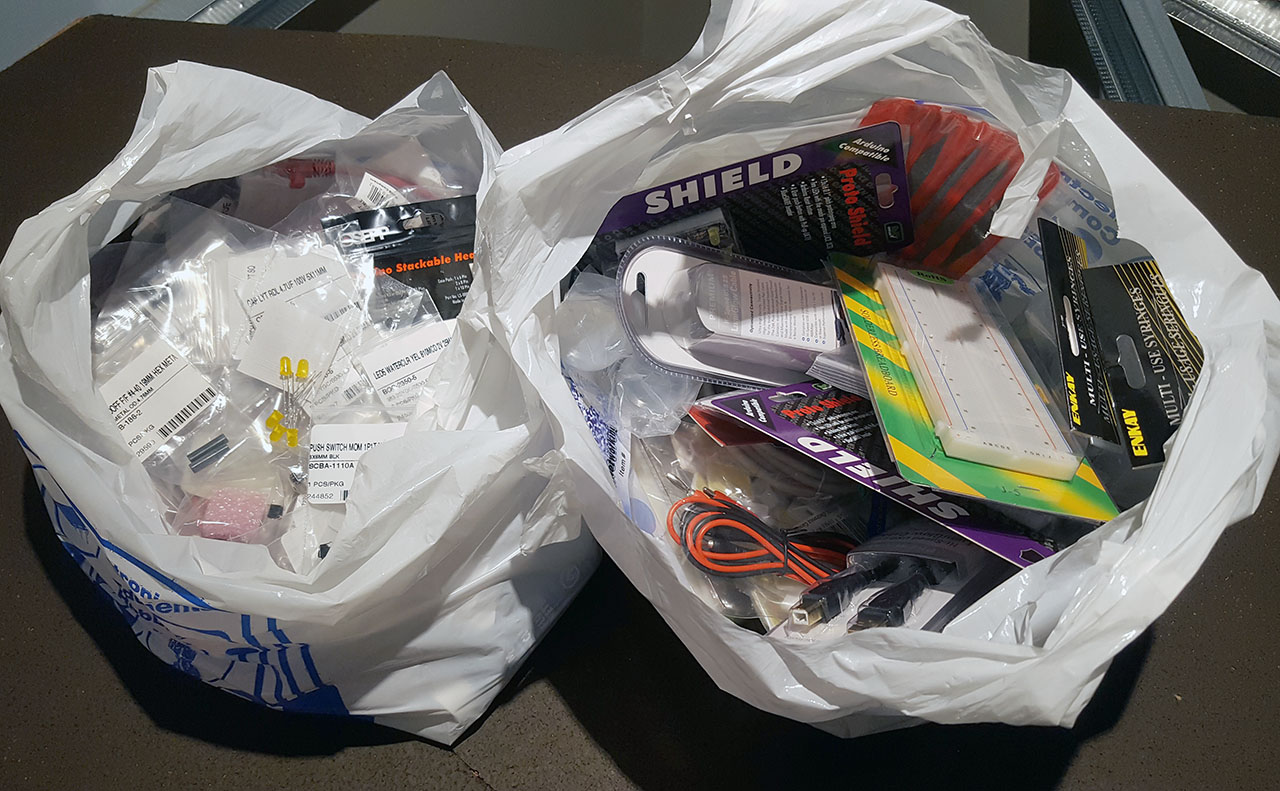
As it always happens (of course), I did not have all the necessary electronics parts to complete the circuits, to my satisfaction, so I went today to look for more. I came back with two bags of various items. Some that I needed to get and some…that were nice to have.
Through serendipity (or forethought), I ended up having on hand an Arduino and a CANbus shield so that was an easy part. Getting a good CANbus driver, and integrating it to work into development code from OpenLCB, well, that’s a different story.
I’m not used to dumbed down IDEs and development setups, and God knows why I decided to use Arduino IDE. I supposed I was lured by the ease of getting some of those commonly used libraries. Heck, even a DCC library is available at a click of a button.
The OpenLCB code I got from David Harris’s GitHub repo. As he states in the opening sentence of the repo, it’s in development and meant for TivaCAN and AT90CAN boards, as that’s where he appears to be focusing the efforts right now. Clearly does not mention Arduino Uno with CAN-BUS Shield. Sounds good, let’s proceed… ;)
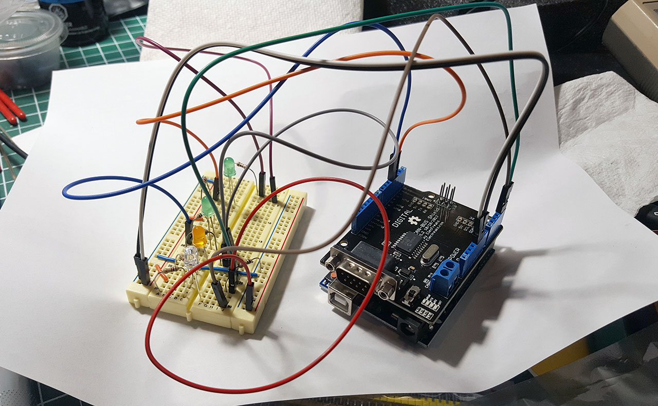
My original (ghetto) setup is below, although now that I got more components in those bags, I’ll be able to replace some of those wires with real buttons. Matter a fact, I bought two Arduino prototyping shields so I’ll build the necessary Button LED circuits on them.
After a few days of struggling with mess of code, dependency hell, and the way Arduino IDE works, I got it all compiled and…not exactly working as intended. I am not sure at this point what I should be seeing from the basic node.
A loopback test of CAN-BUS Shield on its own appears to be working. I do have another set of Arduino Uno and CAN-BUS Shield that I will put together and network with the first one so I can perform a real send/receive CANbus test. Then at least I’ll know the driver is working correctly. Afterwards, I’ll connect the OpenLCB node to RR-CirKits LCC Buffer-USB to create a real LCC network and check if this node would register in JMRI.
You might wonder by now why all this. In an earlier post, I mentioned I got a bunch of modules from RR-CirKits and intend to deploy LCC on my layout. I will be needing *a lot* of LCC electronics if I’m going to accomplish my grand plan. If I can save some money, at the expense of some time, I might end up with a setup I want plus knowledge about OpenLCB/LCC, among other things.
On the other hand, all these side-quests take me away from working on the layout…I’ve still not laid any track down, despite being dead-set to lay track for Yard A in the staging by the end of this year. Maybe I’m wary of doing it because I don’t have a definitive plan for block detection, short circuit protection and controlling track power yet.