The Helix, part 1 of many?
A number of people had suggested I start with the helix because there’s no moving it, if things need to line up with the rest of the yards, as opposed to moving a few yard throat turnouts inch here or there. So I heeded that advice and we are on our way towards building the helix.
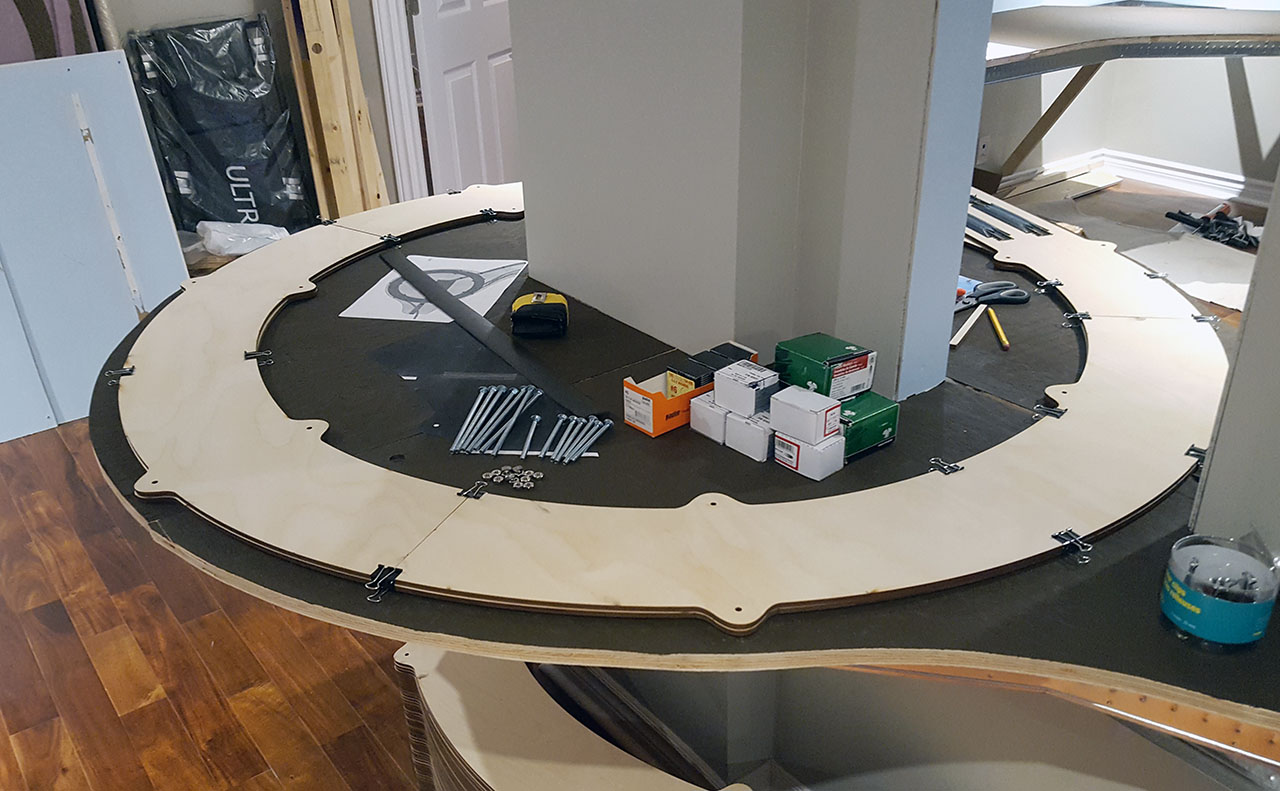
I decided to mock up a loop and test how segments fit together, and whether all stays put when secured with binder clips (it does).

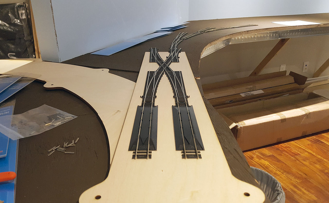
I also had to get an on-ramp laser cut last week too, which was another quick side-project. I’m please to say I did not mess that one up as there was no room for error. Getting the angle wrong on the ramp would mean that helix would align to the yard throat and everything would be off.
It is important to test the clearances as well as the elevations of the first loop at each segment, which define the grade across the entire helix.
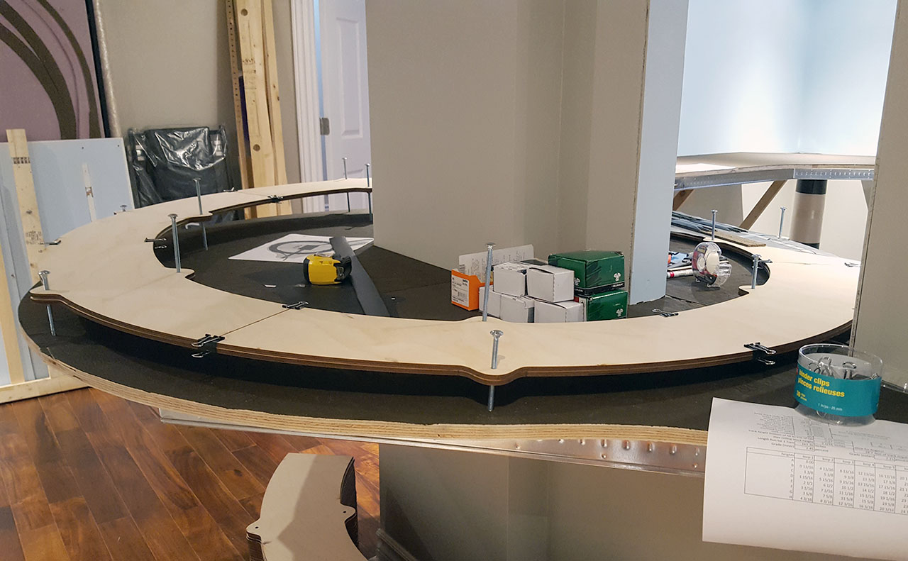
So far so good! I took the tallest car I have on hand (a modern autorack) to see what space is left between its roof and the bottom of the next loop. I was concerned that if I use cork as roadbed, there might not be much space left. That worry has been alleviated as well.
I’m also concerned with noise/vibrations transferring from the helix structure to the benchwork. Since my benchwork is metal studs with 3/4″ plywood on top, I feel that if I just jam the T-nut directly into the benchwork plywood, all the vibrations from the helix will transfer via threaded rods onto the benchwork, creating one big, loud drum. Ugggh…
A few options transpired, one was using acoustic isolation washer bushings at each connection of the helix segment with a threaded rod, but there are 112 of those (14 holes x 8 loops) and at $6/ea. for the bushing, I’m looking at a lot of money spent.

I also thought about using caulk, by making the hole larger then filling the space around the threaded rod with caulk. I decided against that because caulk might disintegrate from pressure or over time, not making it a solid solution.
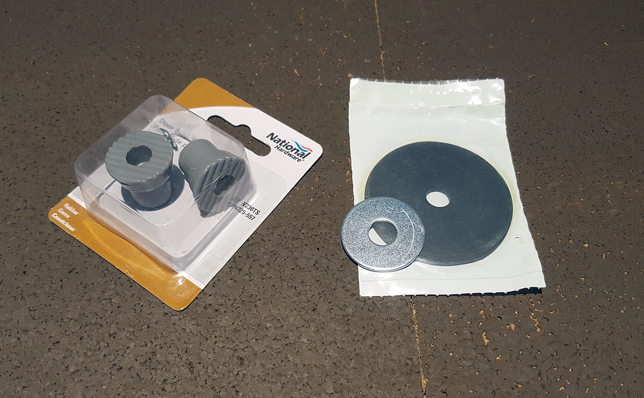
I opted to instead try to decouple the entire helix structure from the benchwork, at the base of mounting. Since the structure is probably going to be heavy, normal rubber might not work. So I found hard rubber door stops of the right size and diameter at local Lowers. I also got some rubber washers that will mount from the bottom along with a fender washer, and everything *should* work out. The door stop will keep the rod away from the plywood and provide some isolation, while also offering enough resistance to the structure above it.
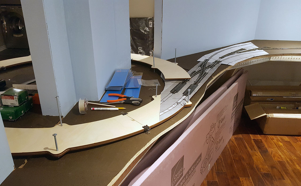
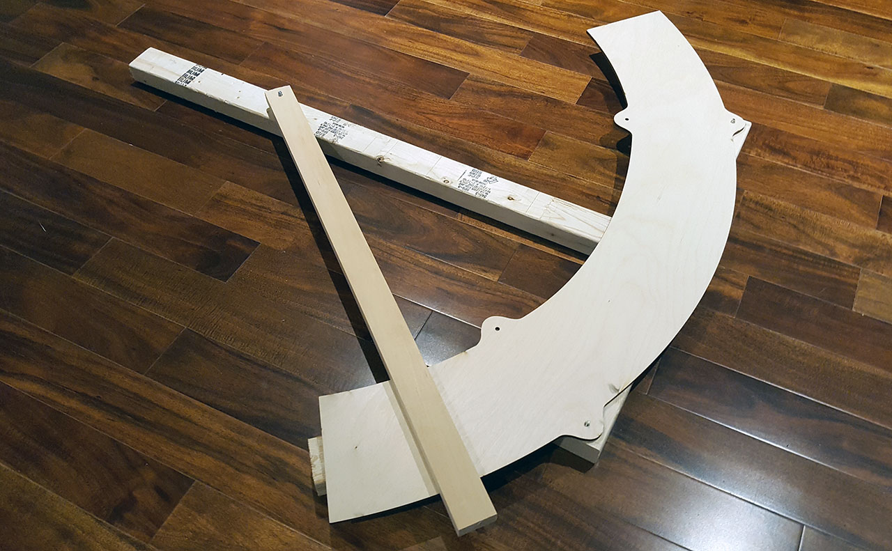
The dweeb I was not thinking ahead, I forgot to have the laser cutting shop inscribe the radii of my curves onto the plywood helix segments. So, another side project was to make a jig that I could use to (accurately) draw track centers of appropriate radii onto 55 segments. It was important to ensure that the segment lays flat and still, so that the lines are correct and match on the edges. I still need to make the holes for a permanent marker…
Lastly, since I’m a sucker for punishment (after all who in their right mind builds a helix around a support column) marking the mounting holes for the threaded rods is not going to be easy. Most people would just build a temporary cross at the center of the helix structure and use a piece of twine to determine equal distances for the 14 mounting holes. My center is in the middle of a brick column, thank you very much.
Here comes another jig, this one even more fun – it has to be pretty dead accurate or the holes in the plywood segments won’t match and the whole deal is off.
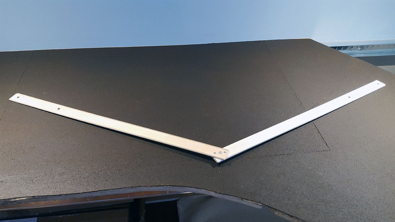
These two pieces of wood actually have a specific angle, and the distances from the middle point (large screw) which is a current hole, towards the left and right mounting hole.

It’s actually two in one, and can be used to determine both inner and outer mounting hole.

I still need a starter point, actually two of them, which are the most critical in determining the rest. Either way, I have not tried this jig yet, so we’ll see how it all goes.
More to come…